Selecting an Air Circuit Breaker Panel is a risk-control decision, not merely a purchasing task. The right panel must coordinate protection, withstand fault energy, support maintenance, and match the installation environment. A polished enclosure means little if its interrupting capacity is too low.
The International Energy Agency’s Electricity 2024 report projects strong growth in global electricity demand through 2026, driven partly by data centers, industry, and electrification. This growth increases pressure on distribution equipment. Uptime Institute’s Annual Outage Analysis 2024 also continues to identify power-related failures as a major source of critical-facility disruption. These findings make breaker selection more important than appearance or initial price.
This guide presents seven practical tips for evaluating an Air Circuit Breaker Panel. It considers rated current, short-circuit capacity, protection settings, selectivity, enclosure design, maintenance access, and certification. IEC 60947-2 provides a key reference for low-voltage circuit breakers, while NFPA 70B emphasizes documented electrical maintenance practices. Use both as technical foundations.
Details matter.
A panel installed in a dusty factory may need stronger enclosure protection than one serving a clean office. A data-center panel may require tighter coordination and clearer alarm visibility. Even experienced teams can overlook temperature derating, cable termination space, or future load growth. No checklist is flawless. However, a disciplined review can expose weak assumptions before they become expensive failures.
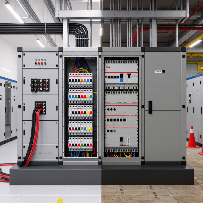
Before selecting an air circuit breaker panel, define the electrical load it must carry. List motors, heaters, lighting, control equipment, and future additions. Record each load’s voltage, phase, rated current, and starting current. A pump may draw far more current during startup than its nameplate suggests. Use measured readings when possible, not assumptions. This step feels basic. It prevents undersized protection and unnecessary interruptions.
Calculate continuous and intermittent demand separately, then apply the required design margins under local electrical rules. Confirm whether the panel will serve a commercial facility, workshop, or outdoor installation. Short-circuit current matters. The breaker’s interrupting rating must exceed the available fault current at the installation point. Ask a qualified engineer to verify feeder length, conductor size, grounding method, and coordination with upstream devices. A neat drawing helps, but field conditions can disagree.
Check system requirements beyond amperage. Confirm enclosure rating, ambient temperature, altitude, service access, arc-flash procedures, and cable-bending space. Leave room for expansion if the facility may add a compressor or charging equipment. Select trip settings that protect conductors without causing nuisance trips during normal starts. In field reviews, a panel may pass a desk check yet fail commissioning because the starting sequence was ignored. Recheck that sequence with real operating data. Small omissions become expensive.
| No. | Selection Dimension | What to Define | Reference Data or Calculation | Practical Panel Requirement | Priority |
|---|---|---|---|---|---|
| 1 | Calculate the connected load | List motors, heaters, lighting, receptacles, converters, and other loads. Record rated power, quantity, operating hours, and duty cycle. | For three-phase loads: I = P ÷ (√3 × V × PF × η) where P is watts, V is line-to-line voltage, PF is power factor, and η is efficiency. |
Select a panel and main breaker that can accommodate the calculated maximum demand current, with documented allowance for future expansion. | Critical |
| 2 | Confirm system voltage and phase | Identify nominal voltage, frequency, phase configuration, grounding arrangement, and whether loads are line-to-line or line-to-neutral. | Typical systems may include 400/230 V, 480/277 V, 208/120 V, or other locally permitted ratings at 50 or 60 Hz. | The air circuit breaker voltage rating must be equal to or greater than the system voltage. Verify pole count, neutral arrangement, insulation level, and frequency compatibility. | Critical |
| 3 | Size the continuous current rating | Determine the highest expected continuous current and account for ambient temperature, enclosure conditions, conductor ampacity, and applicable correction factors. | A continuous load is commonly evaluated over a sustained operating period. The required rating must follow the applicable electrical code and equipment instructions. | Choose an adjustable or fixed long-time pickup suitable for the calculated load. Do not use a higher breaker rating to compensate for undersized conductors. | High |
| 4 | Evaluate short-circuit duty | Obtain the available prospective short-circuit current at the panel location from a fault-current study or the supply utility. | The breaker interrupting rating, such as an Icu/Ics value or an equivalent short-circuit rating, must meet the calculated fault level. | Specify an enclosure, bus system, and air circuit breaker assembly with adequate short-circuit withstand and interrupting capability for the installation point. | Critical |
| 5 | Coordinate protection settings | Review long-time, short-time, instantaneous, and ground-fault functions in relation to downstream breakers and upstream protection. | Time-current curves and selective-coordination studies help reduce unnecessary outages while preserving fault-clearing speed. | Use an adjustable trip unit when the installation requires coordination. Confirm that the minimum instantaneous setting does not compromise equipment protection. | High |
| 6 | Check installation environment | Define ambient temperature, altitude, humidity, dust, corrosive agents, indoor or outdoor location, and required enclosure protection. | Altitude, temperature, ventilation, and contamination can affect insulation performance, heat dissipation, and current-carrying capacity. | Apply manufacturer derating data and select an enclosure with a protection level appropriate to the site. Provide clearance for heat dissipation and maintenance. | Medium |
| 7 | Plan capacity, maintenance, and compliance | Define spare ways, busbar expansion, metering, remote operation, interlocking, test access, and the required design or certification standard. | Common reference frameworks include IEC 60947-2 or the applicable national standard. The final design should be verified by a qualified electrical professional. | Allow practical working space, clearly identify circuits, provide safe isolation, and reserve capacity for foreseeable load growth without exceeding thermal or fault ratings. | Medium |
List motors, heaters, lighting, controls, and planned additions. Record voltage, phase, rated current, and starting current. A pump may surge during startup.
Actual readings reveal hidden demand. Nameplate values can miss starting surges or unusual operating conditions. Small assumptions can cause large interruptions.
Calculate them separately. Apply the required design margin under local electrical rules. Avoid sizing only from the highest nameplate value.
Check nominal voltage, frequency, and insulation level. A 400-volt system needs equipment tested for that duty. Small differences matter.
The rating should exceed normal demand without encouraging oversized conductors. Check cable ampacity and ambient temperature. Crowded enclosures can reduce usable capacity.
Obtain the prospective fault current at the panel location. The interrupting capacity must exceed that value. Higher current ratings do not always mean stronger fault performance.
They describe short-circuit breaking performance under applicable testing requirements. Check the relevant values under IEC 60947-2. Keep test reports with panel records.
The intended protective device should operate first during a fault. Upstream tripping can interrupt more equipment than necessary. I once treated coordination as paperwork; testing proved otherwise.
Check enclosure rating, temperature, altitude, service access, grounding, and cable-bending space. Leave room for a future compressor or charging unit. A neat drawing can still mislead.
Review trip settings against conductor protection and real starting sequences. Recheck field conditions during commissioning. The desk calculation may not tell the whole story.
Choosing the right Air Circuit Breaker Panel begins with a clear understanding of the electrical load, system voltage, operating current, and expected future expansion. The panel should have suitable short-circuit ratings and provide reliable protection against overloads, faults, and abnormal operating conditions. It is also important to evaluate available control, indication, communication, and monitoring functions so the system can be operated safely and efficiently.
In addition, review the panel’s physical design, installation space, ventilation, accessibility, and suitability for the surrounding environment. Consider temperature, humidity, dust, and other site conditions that may affect performance. Before making a final decision, verify that the panel meets applicable electrical standards, supports practical inspection and maintenance procedures, and is backed by dependable technical guidance, documentation, spare parts, and after-sales service. A careful comparison of these factors can improve safety, reliability, and long-term operating value.

 OFA Electrical