Choosing a Dc Circuit Breaker in 2026 demands more than comparing prices, amperage, or attractive product labels. Modern systems combine batteries, solar arrays, electric vehicles, and sensitive control equipment. Each application creates different fault currents, voltage levels, interruption requirements, and installation risks.
Market research shows why this decision matters. MarketsandMarkets projects the global circuit breaker market to grow from approximately USD 8.7 billion in 2023 to USD 12.0 billion by 2028. Grand View Research also identifies renewable energy expansion as a major growth factor through 2030. Meanwhile, the International Energy Agency reported that global renewable capacity additions reached nearly 510 gigawatts in 2023. More direct-current equipment means more complex protection decisions.
A suitable Dc Circuit Breaker must match continuous current, maximum system voltage, interrupting capacity, polarity, trip characteristics, and environmental conditions. The breaker should also comply with relevant standards, such as IEC 60947-2 or UL 489, where applicable. Jim Phillips, P.E., a recognized electrical-safety educator, states, “The best way to protect yourself from an electrical hazard is to eliminate the hazard.” That principle applies directly here.
Small details matter.
A loose terminal can create heat. An underrated breaker can fail during a battery fault. A technically correct device may still be unsuitable for a humid enclosure or high-altitude installation. Manufacturer testing, independent certification, and field experience should guide the final choice. No selection is perfect. However, a documented, standards-based decision is far safer than guessing from a catalog image.
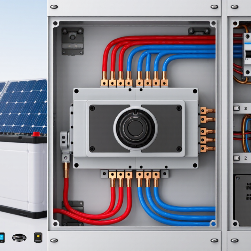
A DC circuit breaker protects conductors and equipment from overloads and short circuits. Unlike AC, DC has no natural current zero crossing. Its arc can continue across separated contacts. Therefore, the breaker needs a suitable arc-quenching design and a verified DC interrupting rating. The rating must match the system voltage, not only the current. For example, a 500 V DC battery circuit requires protection tested at 500 V DC or higher. IEA’s Electricity 2024 report forecasts global electricity demand to grow by an average 3.4% annually through 2026. More batteries, solar arrays, and data systems mean more DC protection points.
Choose the breaker after measuring continuous current, peak load, fault current, cable size, ambient temperature, and installation altitude. Check polarity requirements and the number of protected poles. A breaker rated for 100 A may need derating inside a hot enclosure.
Its interrupting capacity must exceed the available short-circuit current. IRENA’s Renewable Capacity Statistics 2024 recorded 473 GW of new renewable capacity added worldwide in 2023. That growth increases the need for carefully coordinated protection in photovoltaic and storage circuits.
A nominally correct breaker can still fail if the battery fault current was underestimated. This is where practical inspection matters.
Tips: Read the manufacturer’s DC test conditions, not just the front-label rating. Confirm cable coordination and trip curves. Leave space for heat dissipation. If the fault study is uncertain, stop and verify it with a qualified engineer. Small assumptions can create large arcs.
How to Choose a DC Circuit Breaker in 2026?
Identify the system’s voltage, current, and polarity before comparing circuit breaker models. DC systems behave differently from AC systems. The arc can continue after the contacts separate. Therefore, the breaker must match the system’s maximum DC voltage, not only its normal operating voltage. A 48-volt battery system may exceed that value during charging or fault conditions. Check the highest measured voltage and leave a suitable engineering margin.
Measure the continuous load current with real equipment running. Motors, pumps, and inverters may create short starting surges. Select a breaker that carries the expected current without nuisance tripping, but still protects the cable. Confirm the interrupting rating, temperature range, terminal size, and approved conductor type. Polarity matters. Some DC breakers require a specific line and load orientation, especially when their internal arc-control design is directional. Do not guess. Read the technical data sheet and inspect the wiring diagram. In field work, a forgotten charging surge can make an apparently correct selection unreliable.
Tips: Record voltage at the battery terminals and at the load. Measure twice. Check positive and negative connections separately. Compare the breaker rating with the smallest cable in the circuit. If installation conditions are unusual, such as high heat or bundled wiring, apply the manufacturer’s derating guidance. I would also document the chosen values, because memory is not a dependable design record. A careful review may feel slow, but replacing damaged equipment is slower.
| Selection Dimension | What to Identify | Typical Values or Options | Selection Guidance | Verification Point |
|---|---|---|---|---|
| System Voltage | Nominal DC voltage and the highest possible operating voltage | 12 V, 24 V, 48 V, 60 V, 125 V, 250 V, 500 V, 750 V, or 1,000 V DC | Select a breaker with a DC voltage rating equal to or greater than the system’s maximum voltage. Do not use an AC-only rating for a DC circuit. | Check the nameplate and technical documentation for the rated voltage, number of poles, and voltage per pole. |
| Continuous Load Current | The normal current carried continuously by the protected circuit | Measured load current or calculated design current in amperes (A) | Choose the breaker rating above the expected continuous load while ensuring the cable and terminals are rated for the same circuit current. | Confirm conductor ampacity, ambient-temperature corrections, enclosure conditions, and applicable electrical codes. |
| Breaker Current Rating | The current at which the breaker is intended to carry and interrupt the circuit | Common ratings include 1 A, 2 A, 5 A, 10 A, 16 A, 20 A, 32 A, 40 A, 63 A, 100 A, and higher | The rating must protect the smallest current-carrying conductor and remain suitable for the connected equipment. | Do not increase the breaker rating to stop nuisance trips unless the wiring and equipment have been reassessed. |
| Polarity and Current Direction | Whether the breaker is polarized and whether current direction matters during interruption | Non-polarized DC, polarized DC, positive conductor switching, negative conductor switching, or two-pole isolation | Follow the marked line/load or positive/negative terminals on polarized breakers. Use a suitable two-pole device when both conductors must be isolated. | Review the wiring diagram and confirm that the installed orientation matches the manufacturer’s connection instructions. |
| Number of Poles | How many conductors must be disconnected during fault clearing or maintenance | 1-pole, 2-pole, 3-pole, or 4-pole configurations, depending on the system design | Use the pole arrangement required by the circuit design and isolation procedure. A multi-pole device should disconnect poles together when simultaneous isolation is required. | Confirm whether the voltage rating applies per pole or across the complete pole arrangement. |
| Short-Circuit Interrupting Rating | The maximum prospective DC fault current the breaker can safely interrupt | Specified in amperes, kiloamperes (kA), or a tested fault-current value at a stated DC voltage | The interrupting rating must be at least equal to the available short-circuit current at the installation point. | For batteries and DC supplies, account for source capacity, internal resistance, cable impedance, and parallel sources. |
| Trip Characteristic | The breaker’s response to overloads, short circuits, and inrush current | Thermal-magnetic, magnetic-only, electronic, or application-specific DC trip behavior | Select a characteristic that tolerates normal startup current but trips quickly enough to protect the conductors and equipment. | Compare the time-current curve with motor, capacitor, inverter, LED, or converter startup requirements. |
| Environmental Conditions | Ambient temperature, altitude, humidity, dust, vibration, and enclosure conditions | Indoor or outdoor installation; normal or harsh industrial environments; elevated ambient temperatures | Apply temperature derating where required and select an enclosure and breaker construction suitable for the environment. | Check the permitted operating temperature, storage temperature, humidity limits, and altitude correction data. |
| Installation and Termination | Mounting method, conductor size, terminal type, and available panel space | DIN-rail, panel-mounted, plug-in, or enclosed; copper or approved conductor types | Ensure the breaker fits the enclosure and accepts the conductor cross-section, lug type, torque, and insulation diameter. | Verify clearance, creepage, terminal torque, wire bending space, and protection against accidental contact. |
| Auxiliary Functions | Whether the installation needs remote operation or status indication | Auxiliary contact, alarm contact, shunt trip, undervoltage release, or remote actuator | Add only functions compatible with the control voltage, wiring scheme, and required safety sequence. | Confirm accessory ratings for DC switching, control voltage, contact arrangement, and fail-safe behavior. |
A DC breaker must match the circuit’s trip curve, interrupting capacity, and operating ratings. The trip curve shows how quickly the breaker responds to overloads. Fast curves protect sensitive electronics, while slower curves tolerate short motor-starting surges. Do not select a curve from current alone. Measure inrush current, cable length, ambient temperature, and the load’s normal start-up behavior. The IEA Electricity 2024 report expects global electricity demand to grow by about 3.5% annually through 2026. More batteries, charging systems, and control equipment will make correct DC protection increasingly important.
Interrupting capacity is the breaker’s ability to stop a fault safely. Compare its DC interrupt rating with the battery’s maximum prospective short-circuit current. A 10 kA breaker is unsuitable for a 15 kA fault source. Voltage ratings also need careful attention. DC arcs do not cross zero naturally, so a breaker rated for 120 V DC may fail at 240 V DC. Check pole configuration, polarity, insulation voltage, continuous current, and derating data. IEC 60947-2 provides a recognized framework for low-voltage circuit-breaker testing, but real installation conditions can still expose weak assumptions.
Tips: Record the source fault current, not only its nominal rating. Verify the trip curve against manufacturer test data. Leave thermal margin. This choice is rarely perfect. Recheck it after upgrades. Many selection errors begin with an optimistic battery estimate.
Choosing a DC circuit breaker starts with the circuit, not the cabinet. Thermal-magnetic breakers suit many general-purpose loads and respond to overloads and short circuits. Hydraulic-magnetic types can offer more stable performance across temperature changes. Fuse-based protection may be simpler, but replacement access matters. Check the DC voltage, continuous current, interrupt rating, and pole arrangement carefully. DC arcs do not naturally pass through zero, so AC ratings cannot be assumed safe.
Mounting affects installation quality and maintenance time. DIN-rail breakers support neat control panels and quick replacement. Panel-mounted units provide stronger mechanical support for larger conductors. Chassis and busbar-mounted designs can reduce wiring length, but they demand accurate alignment. I once overlooked terminal clearance, creating unnecessary bending near the breaker. It worked, but the layout was not service-friendly.
Tips: Measure the enclosure temperature, humidity, vibration, and altitude before selecting a breaker. Apply the manufacturer’s derating guidance, especially in sealed cabinets. Use suitable enclosures where dust or moisture is present. Confirm conductor size and terminal torque during installation. Leave visible space for inspection. Small details matter. A breaker can pass a bench test yet perform poorly in a hot, crowded panel. Recheck the design after installation, because field conditions often differ from the original drawing.
Choosing a DC circuit breaker in 2026 starts with installation standards, not catalogue ratings. For photovoltaic systems, verify IEC 60364-7-712, IEC 60947-2, and the applicable national code. IRENA’s Renewable Capacity Statistics 2024 recorded 473 GW of renewable capacity added during 2023. The IEA’s Batteries and Secure Energy Transitions report also noted about 42 GW of battery storage additions in 2023. This growth increases the need for dependable DC protection. Confirm rated voltage, continuous current, temperature derating, polarity, and prospective short-circuit current. The interrupting rating must exceed the calculated fault current. Do not trust a familiar rating.
Coordination needs more than matching ampere values. Obtain time-current curves for every protective device, then check selectivity between string, feeder, and main breakers. Review cable ampacity, voltage drop, fault paths, and energy from parallel strings. In battery systems, verify bidirectional current behavior and the manufacturer’s protection method. A qualified engineer should review the study against local inspection requirements. Arc behavior can change sharply when current rises. This detail is easy to underestimate.
Maintenance begins during selection. Choose breakers with accessible terminals, clear status indication, and documented inspection procedures. IEC 60364-6 supports systematic verification, while NFPA 70B:2023 emphasizes a documented electrical maintenance program. Record torque values, insulation-test results, trip tests, and thermal images. Inspect dust, corrosion, loose conductors, and heat discoloration. Battery rooms deserve extra attention. A checklist can still miss aging connections after vibration or repeated thermal cycling. Review the schedule after real operating data arrives; the first interval may be wrong.
It protects conductors and equipment from overloads and short circuits. DC arcs can continue after contacts separate.
The breaker must interrupt the actual system voltage safely. A breaker rated only for current may fail at higher voltage.
Measure continuous current, peak load, fault current, cable size, temperature, and installation altitude. Small assumptions can cause large arcs.
Heat can reduce the safe continuous current. A 100-ampere breaker may need derating inside a hot enclosure.
Calculate the available short-circuit current first. The breaker’s interrupting capacity must exceed that value.
Verify polarity, protected poles, parallel-string energy, and bidirectional current behavior. Battery faults can be stronger than expected.
Time-current curves show which breaker trips first. Proper selectivity can isolate one faulty string instead of shutting down everything.
Follow applicable electrical standards and local inspection rules. Confirm cable coordination, voltage drop, fault paths, and terminal torque.
Record torque values, insulation tests, trip tests, and thermal images. Inspect dust, corrosion, loose conductors, and heat discoloration.
No. A checklist can miss aging connections after vibration or repeated heating. Review the schedule using real operating data.
Choosing a Dc Circuit Breaker in 2026 requires more than matching a voltage number. Its primary role is to detect excessive current and disconnect the circuit before overheating, equipment damage, or fire can occur. Start by confirming the system’s operating voltage, maximum continuous current, fault current, and polarity requirements. The breaker must be rated for the circuit’s DC voltage and expected load, with sufficient interrupting capacity to safely stop the highest possible fault current.
Next, evaluate the appropriate trip curve and ratings for the equipment’s normal startup or inrush current. Compare available breaker designs, including thermal, magnetic, or combined protection, while considering mounting space, accessibility, vibration, temperature, moisture, and dust. Finally, verify that installation follows applicable electrical standards and that the breaker coordinates properly with upstream and downstream protective devices. Clear labeling, secure connections, routine inspection, and periodic testing will help maintain reliable protection throughout the system’s service life.

OFA Electrical