Choosing Smart Grid Switchgear for global projects requires more than comparing prices and rated voltage. Buyers must connect technical performance with local grid conditions, maintenance skills, and long-term operating risks. A coastal substation may need stronger corrosion protection, while a high-altitude site may require adjusted insulation performance. Urban projects often favor compact GIS equipment, but rural networks may benefit from accessible AIS designs.
Dr. Massoud Amin, a recognized smart-grid researcher, has said, “The smart grid is not a thing, but rather a vision for a more resilient, efficient, and sustainable electric power system.” This perspective matters when selecting Smart Grid Switchgear. The equipment should support dependable power flow, remote monitoring, fault isolation, and future network upgrades. Buyers should examine short-circuit ratings, insulation levels, operating temperature, arc-resistance, communication protocols, and enclosure protection. IEC alignment is important, but local certification requirements still deserve careful review.
Small details can decide project success. Can technicians replace a mechanism without importing special tools? Does the supplier provide clear wiring diagrams and practical training? Is spare-parts support available after installation? These questions expose weaknesses that brochures often hide. A low purchase price may become expensive after repeated outages, difficult diagnostics, or unavailable components.
No specification is perfect. A design that works in Germany may perform differently in Kenya, Brazil, or Indonesia. Buyers should request site-based evidence, factory test records, reference projects, and transparent lifecycle costs. This guide explores those decisions carefully, while acknowledging one uncomfortable truth: even well-engineered Smart Grid Switchgear can fail when planning ignores people, climate, and daily maintenance.
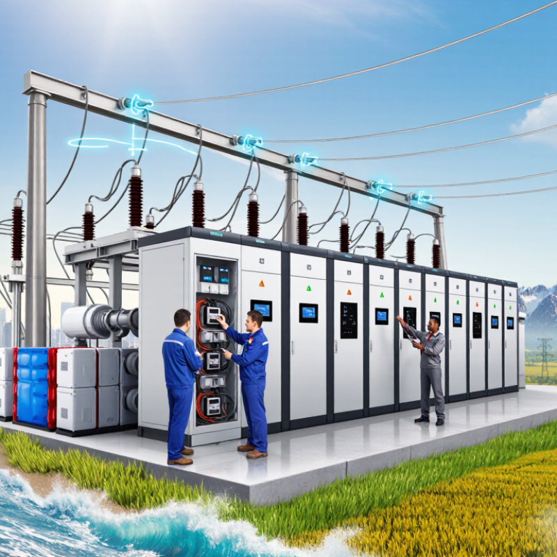
Choosing switchgear begins with the grid’s actual voltage, not a catalog headline. Record nominal voltage, highest operating voltage, fault level, and earthing method. A 11 kV network may require 12 kV-class equipment, while a 33 kV system commonly uses 36 kV or 40.5 kV class gear. The difference matters. Insulation coordination depends on it.
Frequency deserves equal attention. Equipment for 50 Hz and 60 Hz may share a voltage class, but thermal behavior and protection settings can differ. Check breaker current, transformer interfaces, instrument transformer ratios, and relay timing at the intended frequency. Short-circuit withstand ratings should follow the network study, not a convenient standard value. Request test reports and stated test conditions. Small details matter.
Global buyers should verify altitude, ambient temperature, humidity, enclosure rating, cable space, and local installation requirements. A compact 24 kV panel may fit indoors but lose practical clearance at high altitude. A recurring field lesson is easy to miss: rated voltage alone does not define suitability. Future feeder space is useful, although forecasts are often optimistic. A utility-approved data sheet can reduce disputes during manufacturing and commissioning.
Selecting smart grid switchgear starts with the network’s actual electrical profile. Match the IEC 62271 voltage rating to the system’s maximum operating voltage, not only its nominal value. Then select rated current above the expected continuous load, including future expansion and harmonic heating. A 1,250 A panel may suit today’s feeder, but a growing industrial site could need more headroom. Check frequency, altitude, ambient temperature, and enclosure requirements as well.
Short-circuit performance needs closer attention. Confirm the rated short-circuit breaking current and short-time withstand current against the calculated fault level. If the study shows 22 kA for one second, equipment rated 25 kA or 31.5 kA may provide practical margin. Do not select 31.5 kA automatically. Higher ratings can increase size, cost, and installation demands. Review peak withstand current, protection coordination, and the upstream transformer impedance. I have seen projects focus on breaker capacity while overlooking cable fault contribution. That creates an incomplete design.
Tips: Request type-test evidence, routine-test records, and clear IEC 62271 declarations. Ask how ratings change at high altitude or elevated temperature. Confirm that protection relays, current transformers, and switching devices work as one coordinated system. Leave room for uncertainty. Fault calculations are useful, but field data can be imperfect. A qualified engineer should verify the final selection against local grid conditions and the latest project study.
Global buyers should compare AIS and GIS with measured site data, not catalogue slogans. CIGRE studies commonly report GIS footprints at roughly 10–20% of comparable AIS installations. The exact saving depends on voltage, clearances, cable entries, and service roads. Small sites benefit most.
AIS uses atmospheric air and visible insulation distances. It offers easier inspection, but needs wider phase spacing and stronger environmental protection. GIS uses sealed gas-insulated compartments, reducing footprint and limiting exposure to dust, salt, and humidity. IEC 62271-203:2022 defines requirements for gas-insulated metal-enclosed switchgear above 52 kV. Installation teams should verify gas pressure monitoring and maintenance access. Compact is not automatically simple.
IP protection needs careful interpretation. IEC 60529 defines IP54 as protection against harmful dust deposits and water splashes, while IP65 requires dust-tight construction and protection against water jets. These ratings apply to an enclosure, not necessarily the complete substation. An outdoor AIS control cabinet may need IP65, while GIS compartments normally provide stronger environmental separation. Still, cable glands, doors, and ventilation openings can weaken real-world protection. I have seen drawings pass review while drainage details remained unclear. Buyers should request certified IP test evidence, salt-fog data, insulation coordination studies, and lifecycle maintenance records before selecting equipment.
| Evaluation Dimension | Air-Insulated Switchgear (AIS) | Gas-Insulated Switchgear (GIS) | Buyer Selection Guidance |
|---|---|---|---|
| Primary insulation medium | Ambient air provides insulation between energized parts. Solid insulation and insulating barriers may also be used for selected components. | Sealed metal compartments use a pressurized insulating gas, commonly SF6 or an approved alternative gas mixture, together with solid insulation and controlled clearances. | Choose the insulation system according to the required voltage level, environmental conditions, applicable regulations, and the manufacturer’s type-test documentation. |
| Typical installation footprint | Requires larger phase-to-phase and phase-to-earth clearances. Indoor medium-voltage AIS lineups commonly need wider electrical rooms and additional clearance around cable and busbar sections. | Compact sealed construction can reduce the switchgear footprint substantially. Depending on voltage, layout, cable arrangement, and auxiliary equipment, GIS may occupy approximately 30–70% less floor area than a comparable AIS arrangement. | GIS is usually preferable where land, building space, or urban substation area is limited. Request a complete room-layout drawing rather than comparing panel dimensions alone. |
| Common voltage applications | Widely used from low-voltage and medium-voltage distribution systems up to high-voltage substations, subject to the equipment design and applicable standards. | Available for medium-voltage, high-voltage, and extra-high-voltage substations. Compactness becomes increasingly valuable as voltage and required electrical clearances increase. | Compare the rated voltage, insulation level, short-time withstand current, peak withstand current, and power-frequency withstand voltage—not voltage rating alone. |
| Lightning impulse withstand level | Must be verified from the equipment nameplate and type-test certificate. Required clearances can make the overall installation larger at higher insulation levels. | Controlled gas spacing and solid insulation allow high insulation levels within a compact enclosure. The exact value remains design-specific and must be confirmed from the type-test certificate. | Use the required LIWV/BIL for the network and altitude. Do not infer insulation performance solely from AIS or GIS classification. |
| Protection against solid objects and water | Indoor metal-enclosed AIS commonly uses enclosure protection such as IP4X or higher. Outdoor designs may use IP54 or IP55, depending on rain, dust, and ventilation requirements. | Sealed GIS primary compartments commonly use high enclosure protection, often IP65 or higher for the gas compartment. Auxiliary and operating-mechanism compartments may have different ratings, such as IP54. | Confirm the IP rating separately for the primary compartment, cable box, operating mechanism, control cabinet, and ventilation openings. |
| Dust and moisture exposure | More exposed insulation surfaces can require greater attention in dusty, humid, saline, or chemically aggressive environments. Anti-condensation heaters and space heaters may be required indoors. | Primary energized parts are enclosed and less exposed to external dust, humidity, and pollution. External interfaces, cable boxes, and control cabinets still require suitable environmental protection. | GIS generally offers stronger primary insulation protection in polluted or space-constrained sites. Verify corrosion protection and sealing for the complete installation. |
| Maintenance access | Components are generally more accessible for visual inspection, testing, and replacement. Isolation and safety procedures remain mandatory. | Primary conductors are sealed and are not normally accessible for routine inspection. Maintenance focuses on gas density, leak monitoring, operating mechanisms, interlocks, and diagnostic testing. | AIS may be attractive where local maintenance capability and rapid component access are priorities. GIS requires trained personnel and suitable diagnostic procedures. |
| Environmental and gas-management considerations | Does not require management of insulating gas in the primary air-insulated compartments. | If SF6 is used, handling, recovery, leak control, and reporting must follow applicable environmental rules. GIS using alternative gases still requires compliance with the specified gas-handling procedures. | For international projects, check the destination country’s rules for SF6, fluorinated gases, recovery equipment, service personnel, and end-of-life disposal. |
| Site and weather suitability | Suitable for many indoor and outdoor substations when clearances, drainage, ventilation, pollution level, altitude, and corrosion protection are properly designed. | Well suited to urban, coastal, polluted, high-altitude, and harsh-weather locations when the enclosure, sealing system, and ancillary equipment are correctly specified. | Evaluate altitude correction, seismic requirements, wind load, ambient temperature, humidity, salt contamination, and flood risk before selecting the enclosure type. |
| Typical project trade-off | Usually provides simpler visual access and can offer lower initial equipment cost, but may require more land, a larger building, and greater environmental exposure control. | Usually provides a smaller footprint and improved primary-compartment protection, but may involve higher initial cost, specialized installation, and gas-management requirements. | Choose AIS for accessible, spacious, and cost-sensitive sites; choose GIS for compact, highly protected, or environmentally challenging installations. |
| Data qualification | Values such as footprint reduction and IP ratings are indicative industry ranges rather than universal specifications. The final selection must be based on the project’s single-line diagram, rated voltage, insulation level, short-circuit duty, environmental class, applicable IEC or equivalent standards, and the manufacturer’s certified technical data. | ||
How to Choose Smart Grid Switchgear for Global Buyers?
Smart grid switchgear must do more than interrupt current. It should exchange precise protection data during a fault. Specify IEC 61850 Edition 2.1, with GOOSE messaging for fast tripping and sampled values for digital measurement. For 50 Hz systems, confirm the selected sampling rate, time synchronization, and network performance. A common 80-samples-per-cycle setting means 4,000 samples per second.
Speed matters. A sub-50 ms fault response can reduce arc exposure, equipment stress, and service disruption. However, this figure should cover the complete chain, not only the relay. Test sensors, merging units, communication switches, logic, and breaker travel together. The International Energy Agency reported in Electricity Grids and Secure Energy Transitions (2023) that over 80 million kilometres of grids must be added or refurbished globally by 2040. Interoperability is therefore practical, not decorative.
Ask suppliers for witnessed FAT results, packet-loss tests, time-sync records, and disturbance files. Check performance under network congestion. Also verify IEC 61850 conformance, cybersecurity controls, environmental ratings, and local grid-code requirements. IEC 61850 does not automatically guarantee a 50 ms trip. That assumption is risky. In field projects, configuration errors often matter more than hardware speed. I would leave margin, document every latency value, and retest after commissioning. Perfect specifications rarely survive site conditions.
How to Choose Smart Grid Switchgear for Global Buyers?
Verify Arc-Flash Safety, Environmental Limits, and Lifecycle Service Requirements
Smart grid switchgear should be selected from site evidence, not brochure claims. Request an arc-flash study using the actual transformer ratings, cable lengths, and fault levels. Check the incident-energy value at each working distance. Verify internal arc classification, pressure relief, grounding, mechanical interlocks, and protection relay coordination. Test procedures must match the delivered configuration.
Safety comes first.
Ask for certified test reports and clear assumptions. A low calculated energy level may change after network expansion. Specify suitable personal protective equipment, remote operation, and visible isolation points. These details matter during maintenance, especially in compact substations with limited escape space.
Environmental limits deserve equal attention. Record the highest temperature, altitude, humidity, salt exposure, dust level, and seismic conditions. At high altitude, insulation clearances may require adjustment. Coastal sites need stronger corrosion protection. Desert sites may need filtered ventilation, sealed compartments, or thermal derating. Do not accept a broad “outdoor rated” statement without test conditions.
Lifecycle service can decide the real project cost. Confirm spare-part availability, firmware support, diagnostic access, training, and response times across the operating region. Ask how obsolete relays will be replaced without redesigning the panel. Maintenance intervals should reflect switching frequency and local conditions. A perfect specification is impossible. However, vague service promises create avoidable risk. Some buyers focus heavily on purchase price, then discover that one unavailable component delays an entire feeder.
Verify arc-flash safety, environmental limits, and lifecycle service requirements before specifying medium-voltage switchgear.
IEC 62271-1 normal service conditions include a maximum ambient temperature of 40°C, a 24-hour average of 35°C, and a minimum of −25°C for outdoor installations.
Request an IEC 62271-200 internal arc classification, such as AFL or AFLR, with the tested current, duration, enclosure access sides, and installation conditions clearly stated.
Confirm maintenance intervals, switching-operation ratings, spare-parts availability, diagnostic support, and service coverage for the intended duty cycle and site environment.
Specify IEC 61850 Edition 2.1 for protection and automation communication. Use GOOSE messaging for fast tripping. Use sampled values for digital measurements. Interoperability is practical, not decorative.
For a 50 Hz system, confirm the selected sampling rate and time synchronization. An 80-samples-per-cycle setting produces 4,000 samples per second. Check whether network performance supports continuous measurement without packet loss. Small settings matter.
It should cover sensors, merging units, switches, logic, and breaker travel. Do not measure only relay operation. Test the complete protection chain together. A fast relay alone proves little.
Request witnessed factory acceptance tests and packet-loss test results. Review time-synchronization records and disturbance files. Test performance during network congestion. Retest after commissioning. Site conditions can be messy.
No. The standard does not guarantee a complete 50 ms response. Configuration errors may create more delay than hardware limitations. Document every latency value and keep reasonable margin. That assumption is risky.
Request a study using actual transformer ratings, cable lengths, and fault levels. Check incident energy at each working distance. Verify internal arc classification, pressure relief, grounding, and mechanical interlocks. Protection coordination must match the delivered configuration.
Record temperature, altitude, humidity, salt exposure, dust, and seismic conditions. High altitude may require adjusted insulation clearances. Coastal locations need stronger corrosion protection. Desert sites may need filtered ventilation or thermal derating. “Outdoor rated” is not enough.
Confirm spare-part availability, firmware support, diagnostic access, training, and regional response times. Ask how obsolete relays can be replaced without redesigning the panel. Set maintenance intervals for switching frequency and local conditions. A cheap purchase can become an expensive delay.
Choosing Smart Grid Switchgear begins with clearly defining the network’s operating conditions. Global buyers should confirm voltage classes from 1 to 40.5 kV, frequency requirements of 50 or 60 Hz, continuous load current, and expected short-circuit levels up to 31.5 kA. Equipment ratings should align with IEC 62271 requirements, while the choice between air-insulated and gas-insulated switchgear should consider available footprint, insulation performance, maintenance access, and IP protection.
Modern grid applications also require dependable automation. Specifications should include IEC 61850 communication, sampled-value support, and protection schemes capable of fault response in less than 50 milliseconds. Before purchase, buyers should verify arc-flash protection, temperature, humidity, altitude, pollution, and other environmental limits. Finally, a complete evaluation should cover installation, testing, spare parts, monitoring, maintenance skills, system upgrades, and end-of-life planning, ensuring safe and reliable performance throughout the switchgear’s lifecycle.

OFA Electrical